Assembly
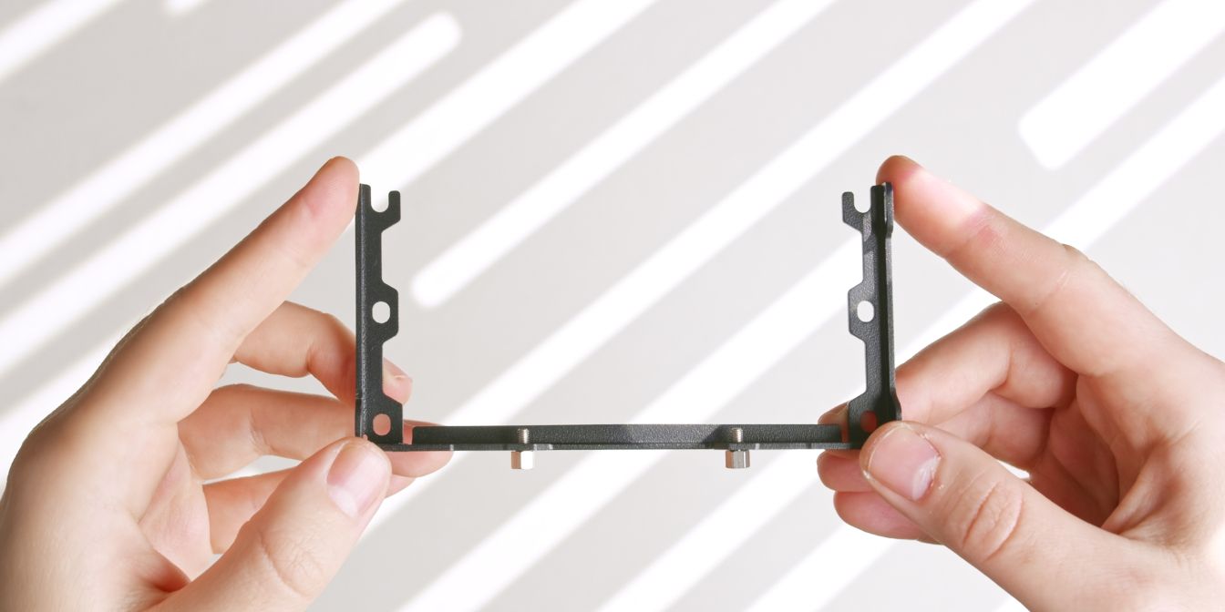
Side Struts
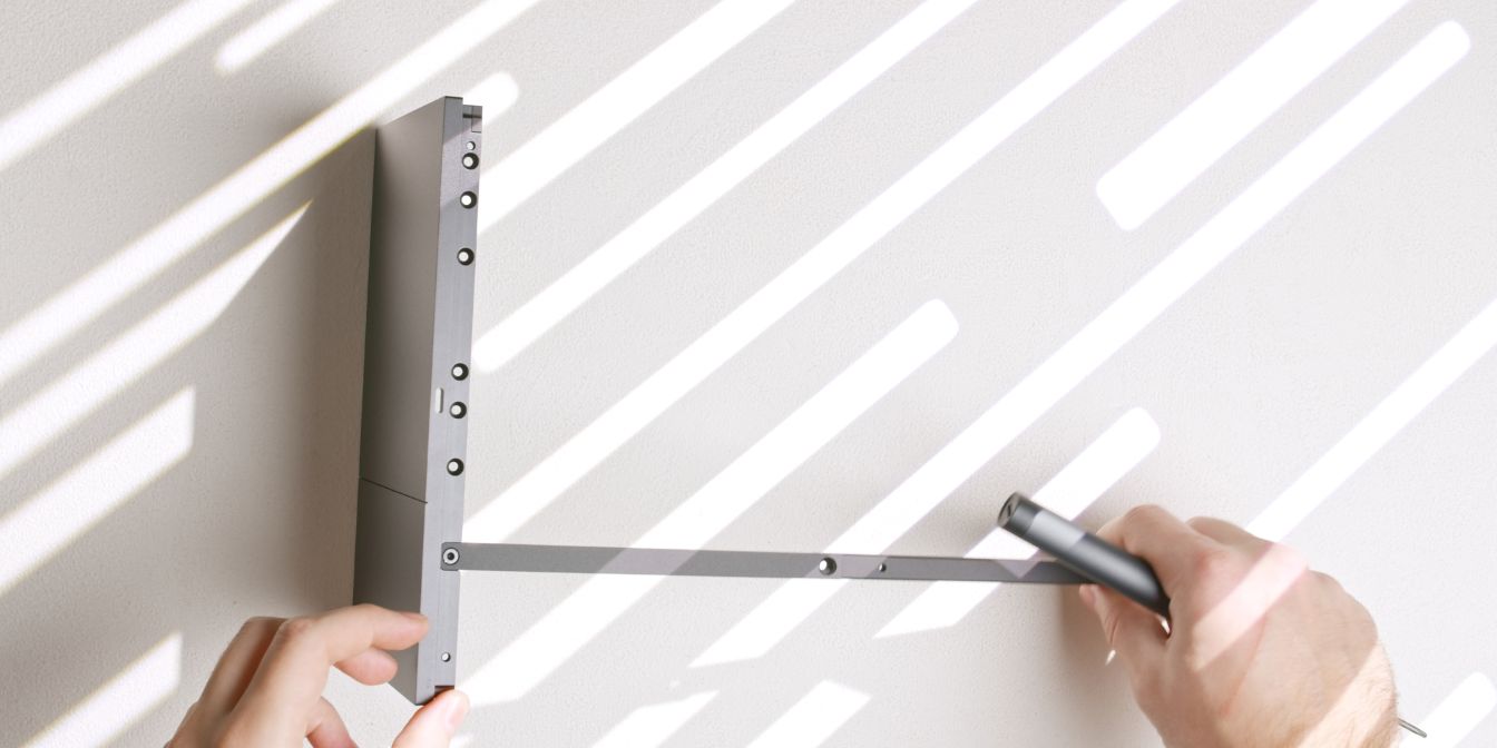
Let’s start by connecting the two side struts to the front panel. Note the orientation of the side struts, the rounded end goes towards the front panel.
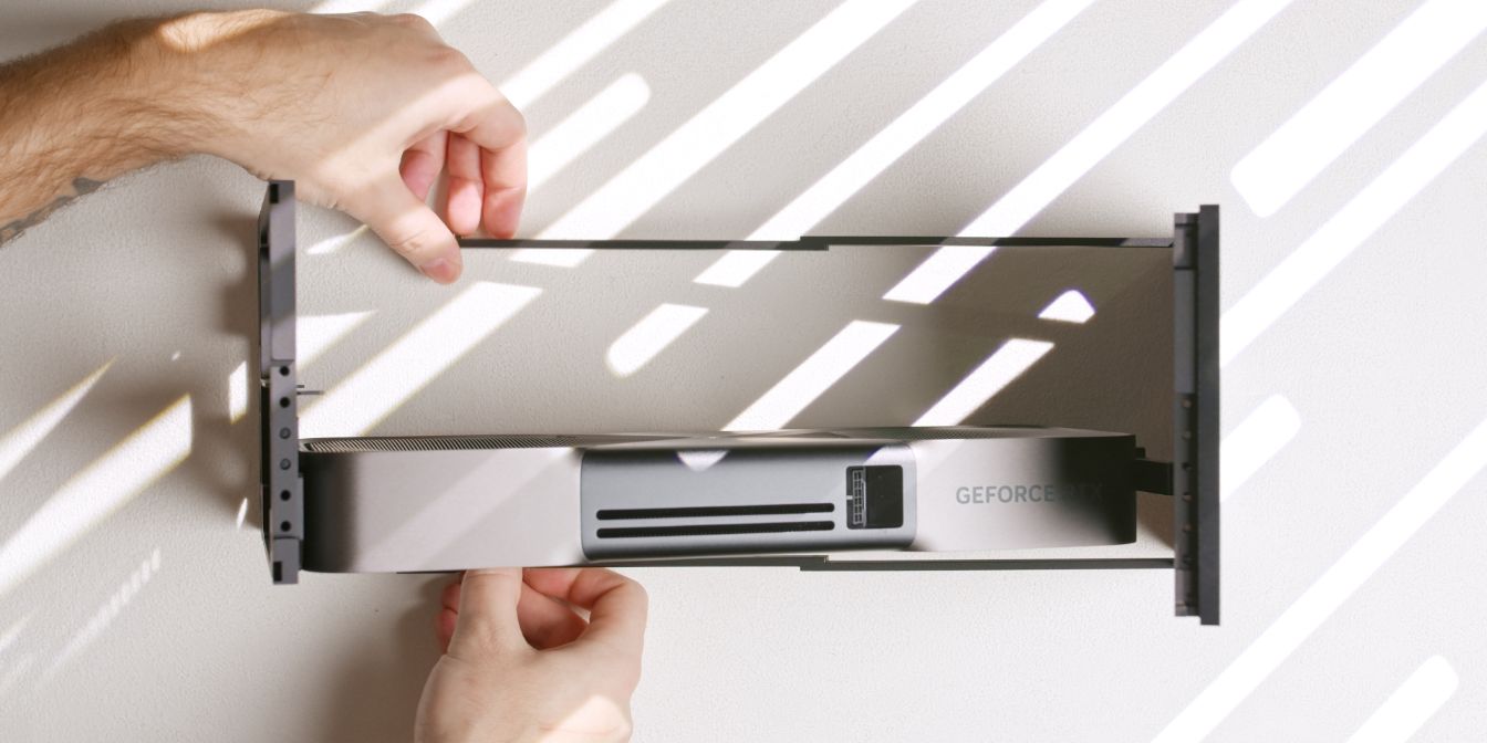
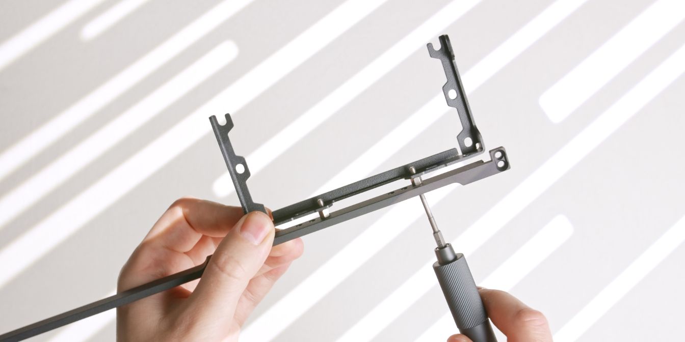
Connect the front panel and rear panel assemblies together using the loosened side struts, being mindful of the GPU anti-sag hook which should go over the top of the front panel.
Secure the side struts to the rear panel and tighten the front panel strut screws left intentionally loose in the previous step.
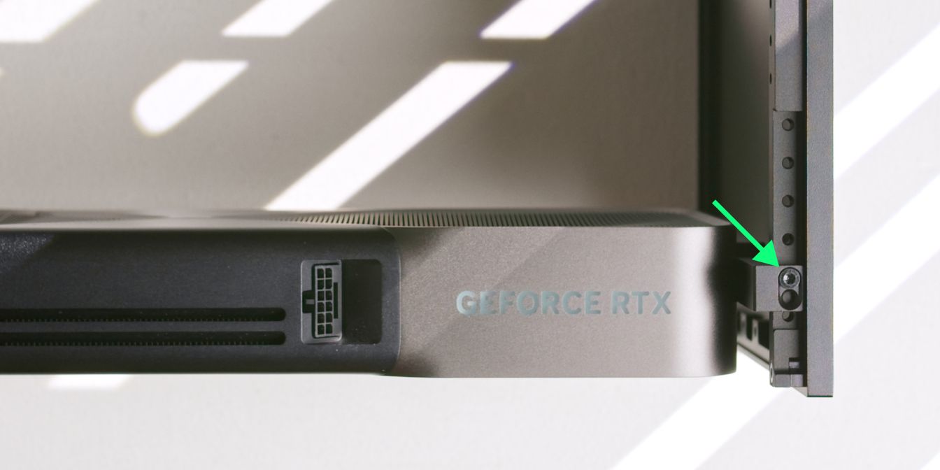
Secure the GPU anti-sag bracket “hook” to the front panel using the “3 slot” configuration as shown in the image above.
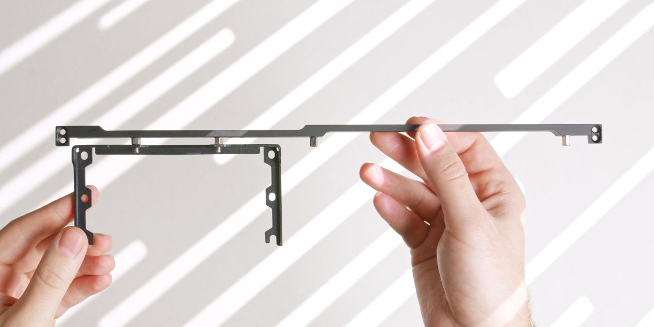
Riser Bracket
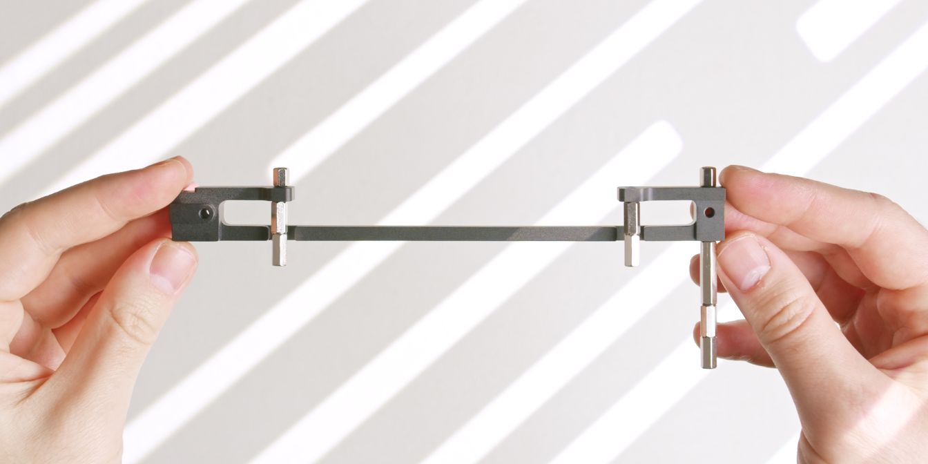
Let’s prepare the riser bar for our 1 slot offset configuration by adding in all the necessary standoffs:
Using the above image as a reference, mount the standoffs to the riser bar.
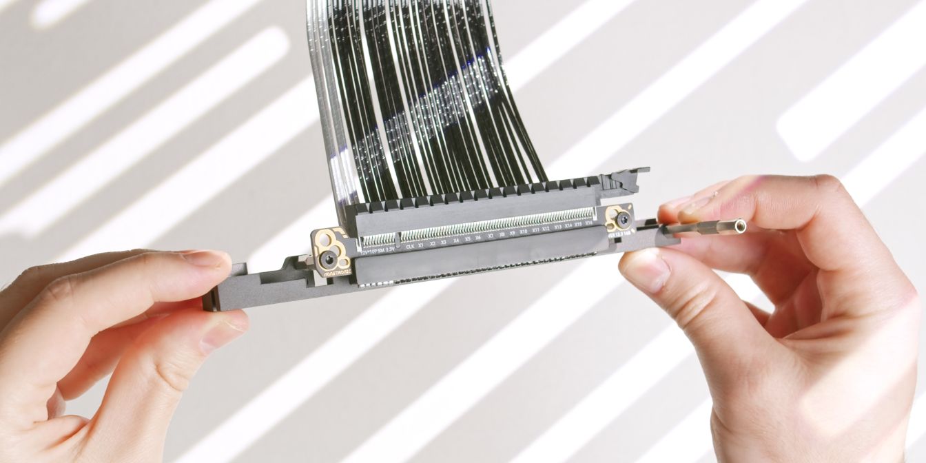
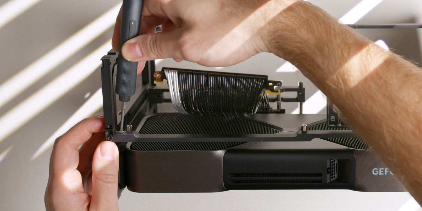
Secure the riser to the riser bar with two M3x4 screws, using the outermost holes on the riser PCB.
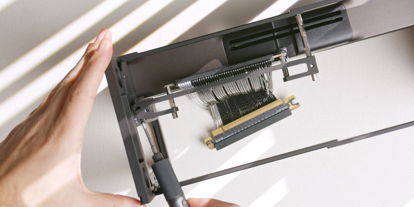
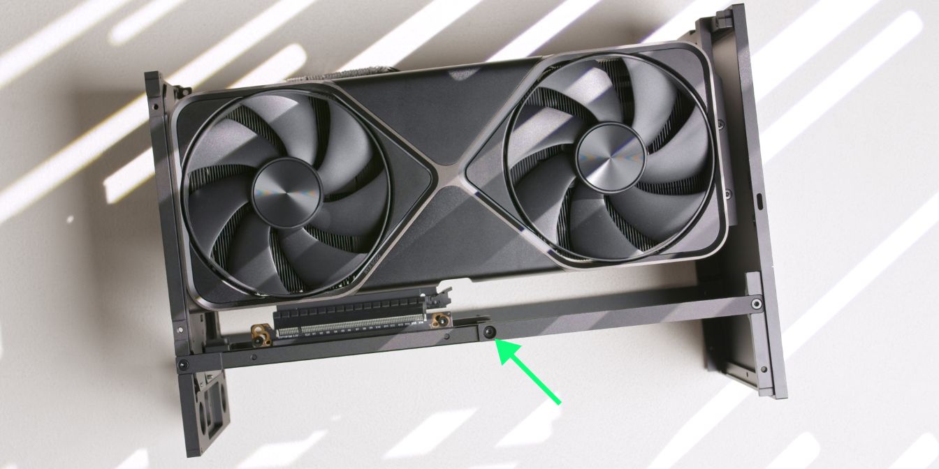
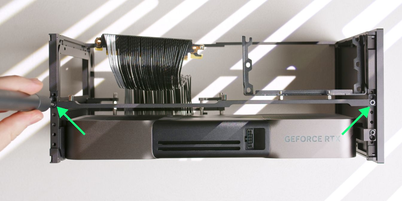
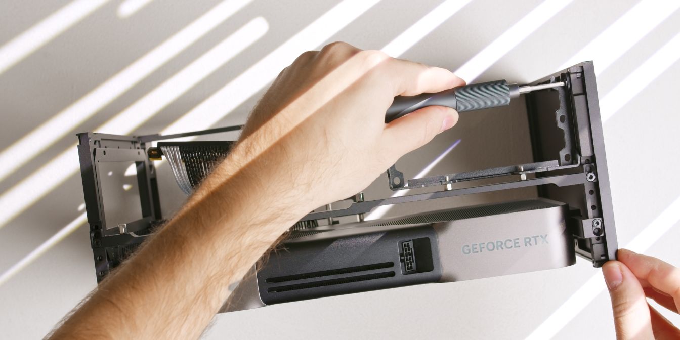
Slot the riser + riser bar assembly onto the GPU PCIe connector and secure it with a side screw connecting to the rear panel insert.
Secure the other mounting point of the GPU riser bar to the side strut.
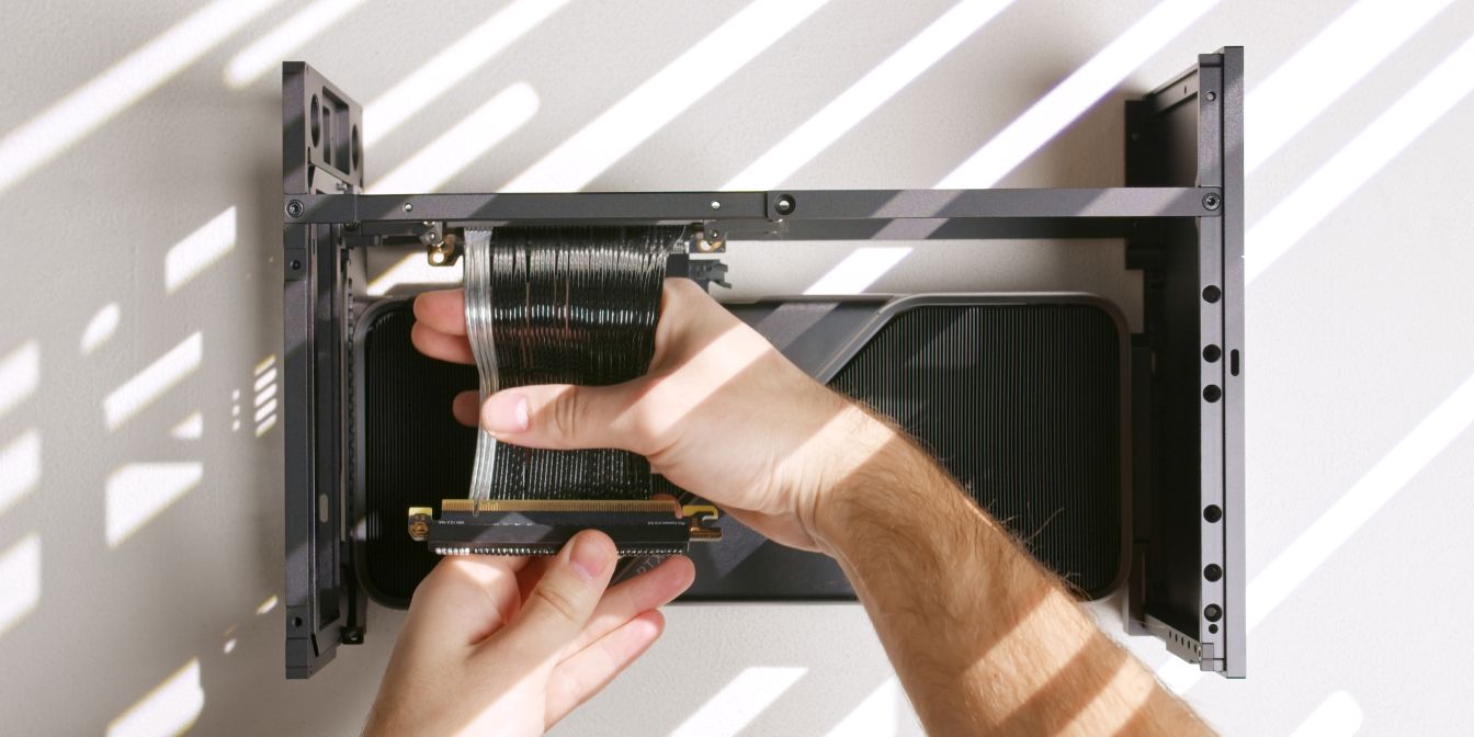
Give the Gen5 riser a slight bend as shown to make the riser bend away from the flow-through exhaust of the 5090 Founders Edition.
PSU Bracket
We can further increase the gap between the 5090 FE flow-through exhaust and the back of the power supply by adding an offset to the power supply bracket.
You can use two of the included M3 5mm standoffs here, but I’m instead using two 4mm standoffs that I’ve sourced separately, this keeps the power supply from touching the side panel.
Use two flat head screws to secure the PSU bracket to the T1 top strut, using the rightmost positions for the bracket holes.
Top Strut
Add two 6mm M3 standoffs onto the top strut using the motherboard mounting holes on the same side as the PSU bracket.
Install the top strut using the second hole position as shown.
Don’t forget about the small screw connecting the top strut to the rear panel…
… and the flat head screw connecting the PSU bracket to the front panel. This will help with rigidity and make the PSU bracket rock solid.
Power Button
Secure the power button cable to the T1’s front panel.
The power button can go on either side of the front panel, so choose a position that works best depending on how you’ll end up positioning the case on your desk.
Power Cable
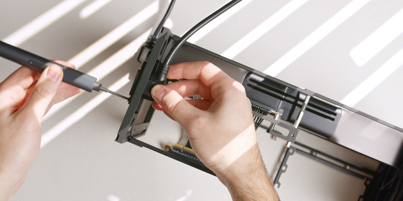
Let’s add the internal power cord extension cable.
Feed it through the rear panel cutout and secure it with two countersunk head screws.
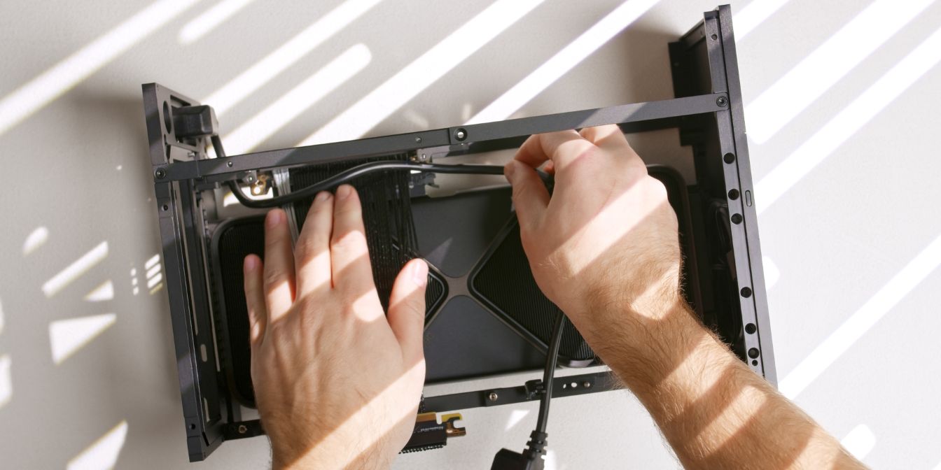
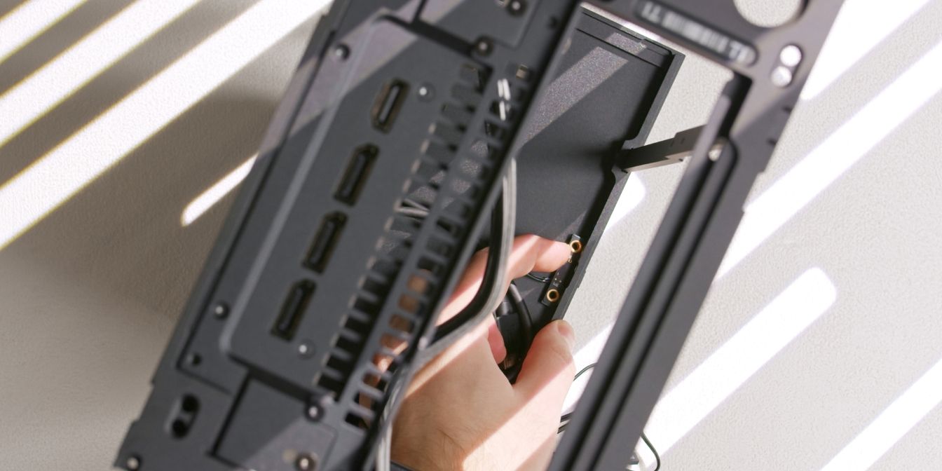
Route the power cable over the riser cable as shown. We’ll be adding the motherboard over it in the next assembly step.
Motherboard
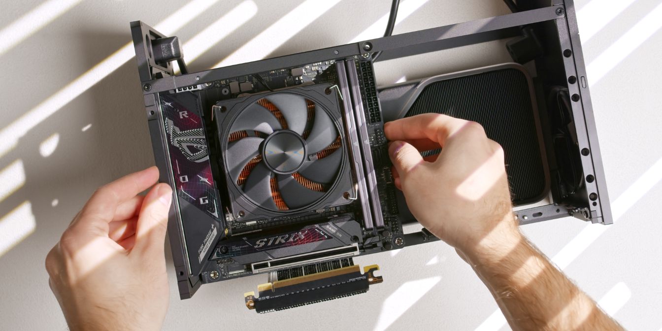
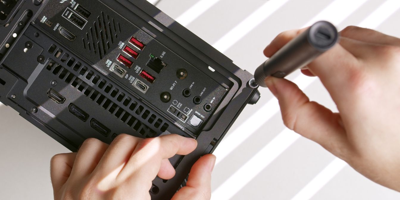
Place the motherboard onto the four M3 6mm standoffs. Insert it at a slight angle to clear the Wi-Fi antenna stubs located on the rear I/O panel.
Secure the motherboard with four flat heat M3x4 screws. Do not over-tighten.
PSU
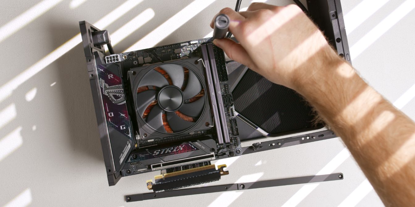
Connect the 12V2X6 power cable to the GPU. Make sure it’s fully seated by listening for the audible “click” of the retention latch.
If you are using the stock Corsair PSU cable, pre-bend the cable slightly so that it naturally curves towards the front panel.
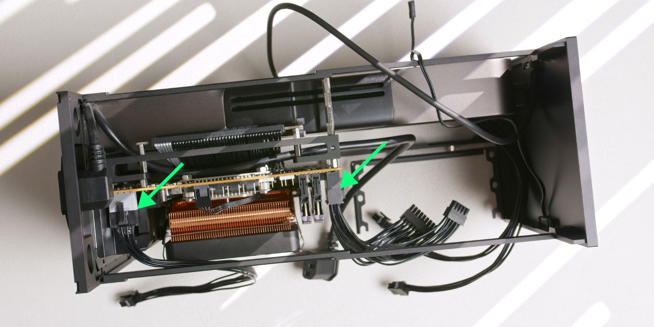
Connect the CPU 8 Pin and the ATX 24 Pin cables to the motherboard.
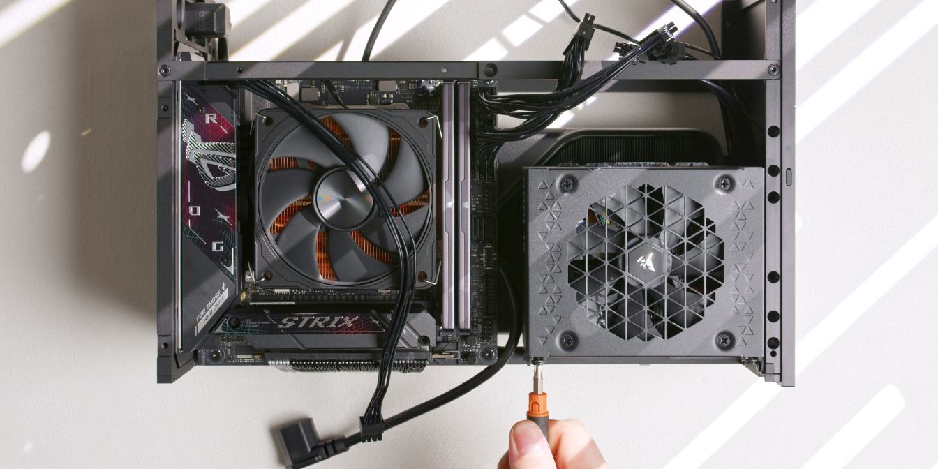
Secure the Corsair SF1000 power supply to the PSU bracket using four PSU screws.
Make sure the PSU is parallel relative to the edge of the front panel, if not, undo the screw connecting the PSU Bracket to the front panel and re-tighten while holding the PSU parallel.
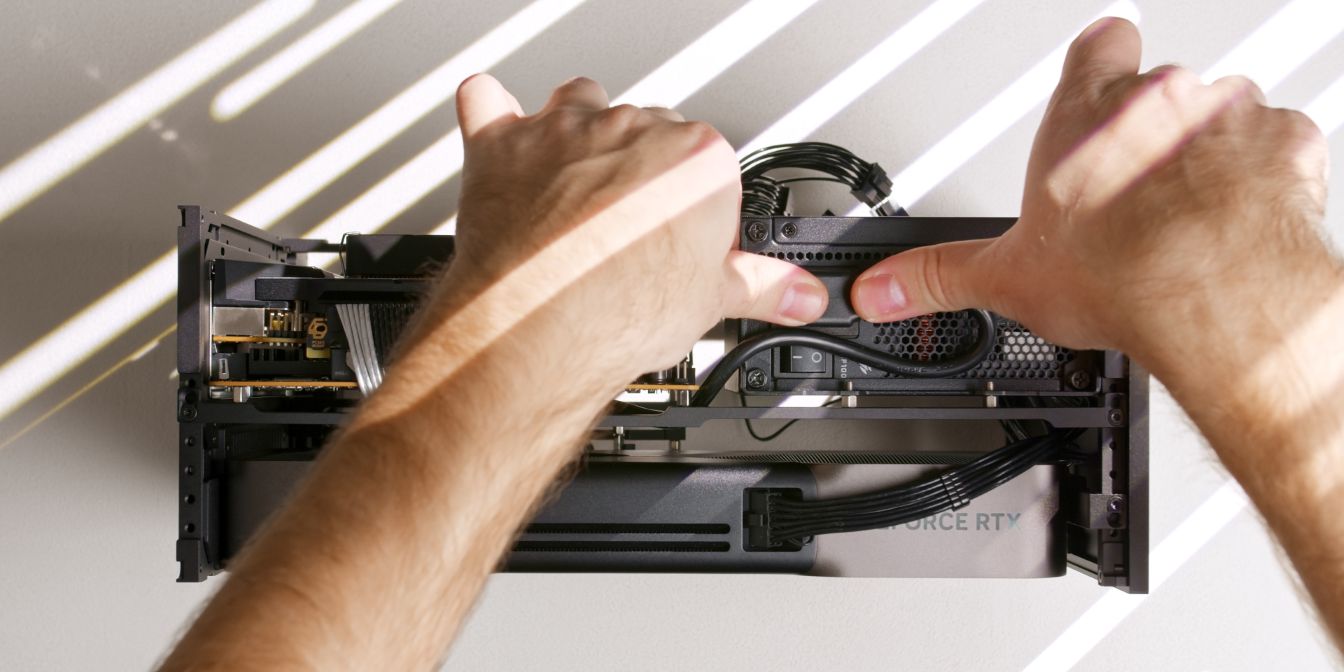
Connect the internal power cord extension cable to the PSU. Bend the extra length towards the top strut like shown.
You can also switch on the PSU power button as it will be harder to do so after we add the bottom panel.
Bottom Panel
Install the included rubber feet in the outermost holes of each of the four corners of the bottom panel.
I use these fancier aluminium Hi-Fi feet (AliExpress) that mount in the exact same way.
Insulating washers between the panel and each screw can be used to protect the panel from scratches, although this is entirely optional.
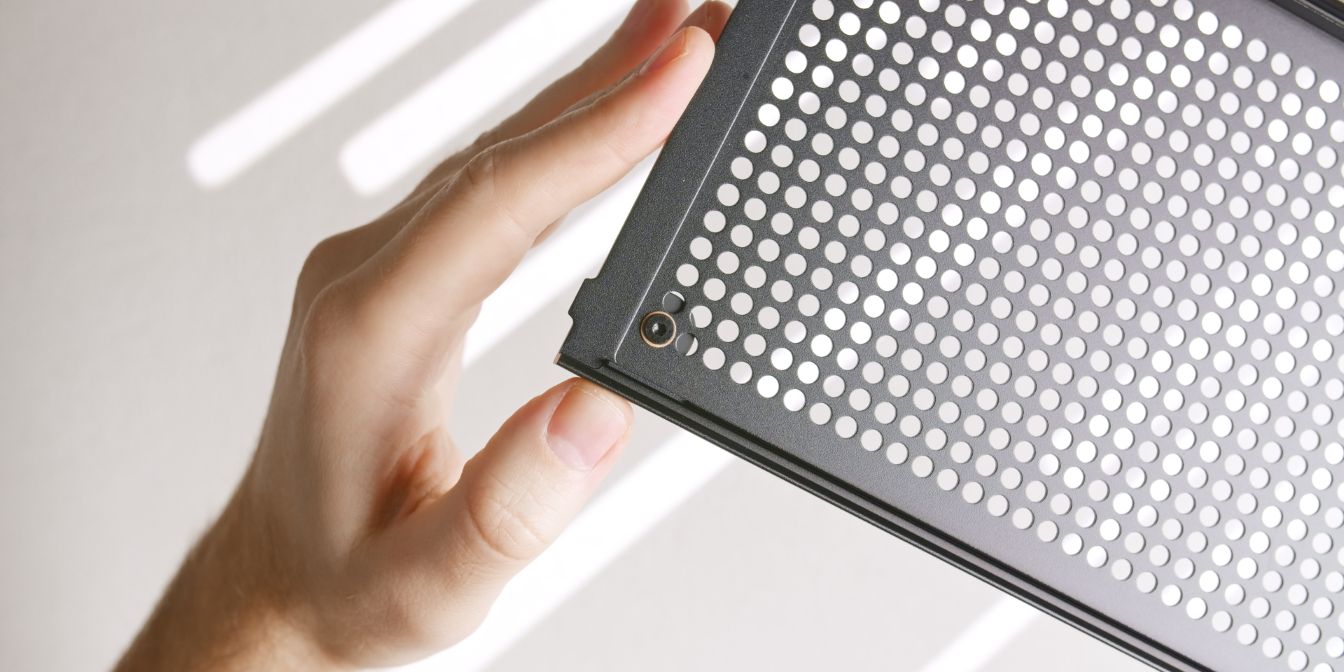
Mount the bottom panel by inserting it into the front panel at a slight angle. Note the two protruding tabs that go underneath the lip of the front panel.
Secure the bottom panel to the rear panel using two of the included M3 thumb screws.
Alternatively, I use 12mm long M3 screws together with countersunk washers. Check out the Screws section for more details.
Cables
Let’s finish connecting the internal cables.
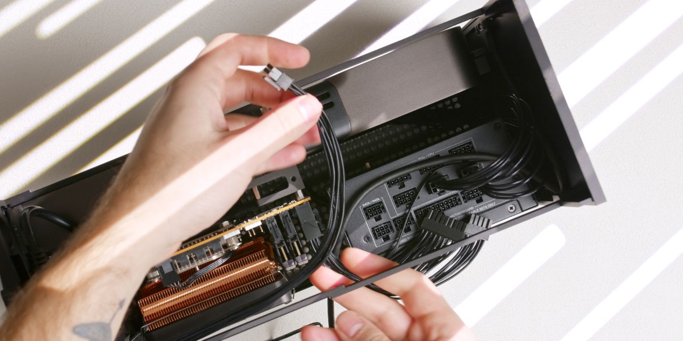
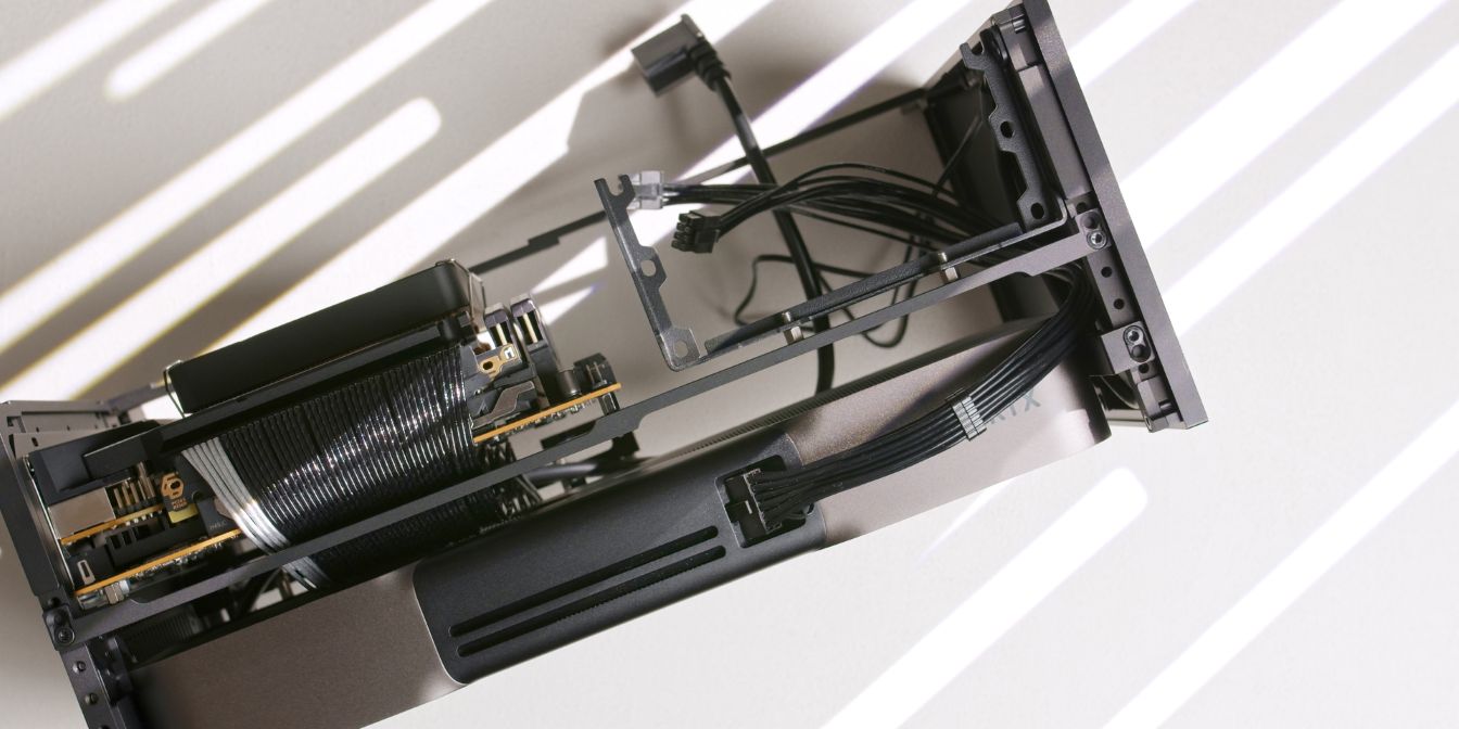
I like routing the Type-C and power cables in between the 8 pin CPU and GPU cables, it helps keep them in place and out of sight.
Connect all the loose ends of the cables we added during the PSU step. You can choose any of the 6 available PCIe/CPU connectors for the 8 pin cables.
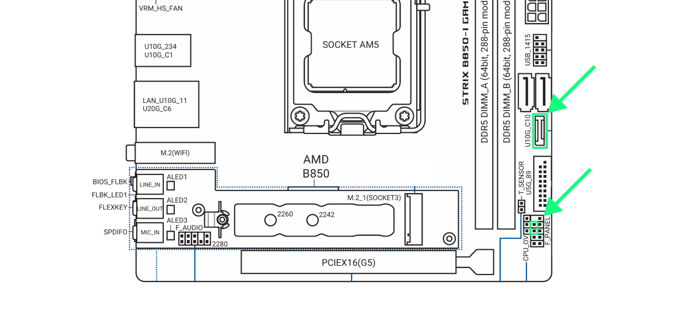
Connect the internal USB Type-E cable to the connector on the motherboard. I give this cable a U-shaped bend that holds it in place against the side of the PSU.
Connect the power button cable to the PWR_BTN header on the motherboard. I tuck the excess length under the PSU, next to the internal power cord extension cable.
Exhaust Fans
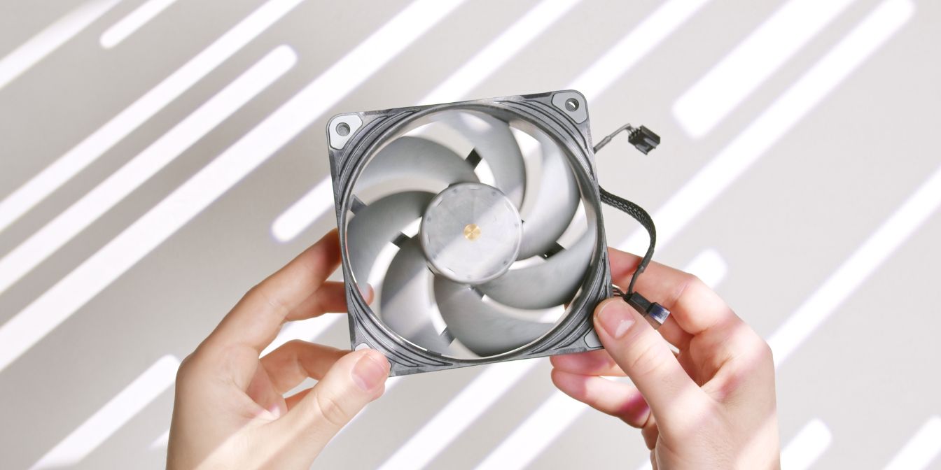
The Phanteks T30 120mm are my preferred exhaust fans for the T1.
If you cannot find any in stock, a solid alternative are the Noctua NF A12x25 G2 (affiliate link), and you can pair them with the NA-IS1-12 inlet spacers (affiliate link) for a slight cooling improvement.
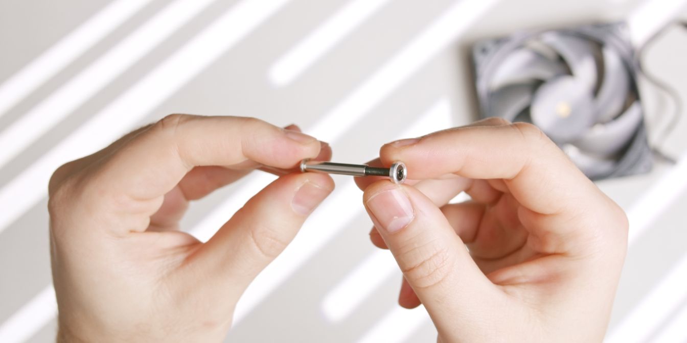
Instead of using standard self-tapping fan screws, I use a much cleaner solution.
You can find kits like these which include M3 barrel nuts, countersunk-style washers, and screws. I find them to be a game changer and fully recommend getting some.
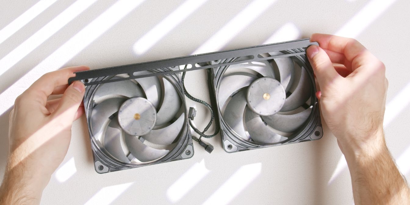
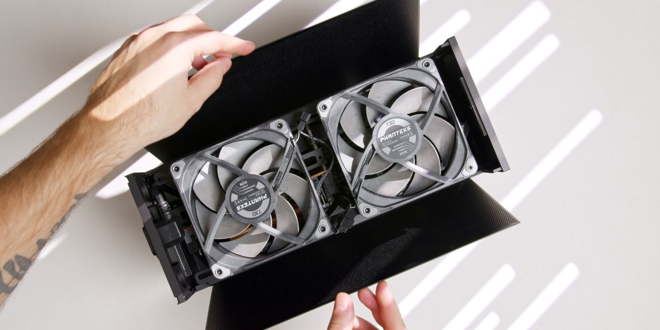
Plug one fan into the other using the daisy-chain 4 pin cable and then place one of the T1 fan brackets over the fans.
We’re working “upside down” here, so the fan inlet sides are facing upwards, and so are the metal brackets.
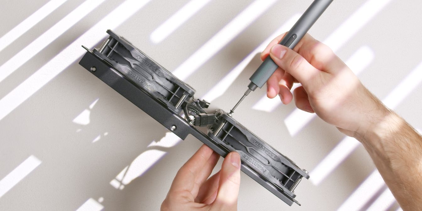
Insert barrel “sleeves” through the fan brackets and into the mounting holes of the fans, then add washer and screws from the other side, threading the screws into the barrels.
Repeat the steps for the other fan bracket.
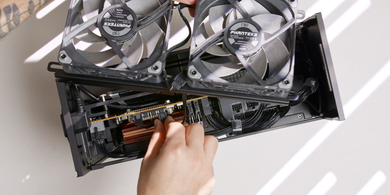
Take the exhaust fan assembly, connect the 4 pin PWM header of the T30 daisy chain to your CHA_FAN or EF_FAN motherboard headers, then rest the assembly onto the T1 side struts.
Tighten the fan brackets onto the side struts using two screws on each side of the T1.
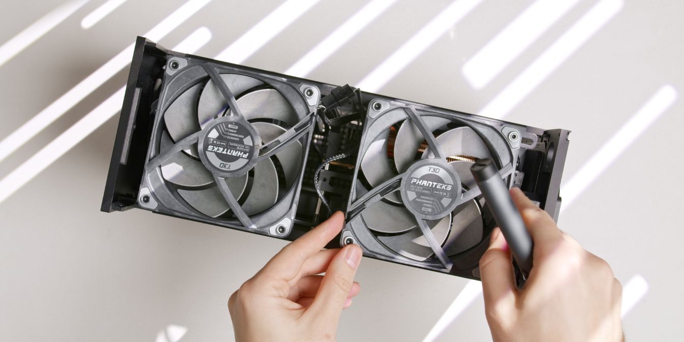
Position the fans left slightly loose to your preference, then fully tighten the fan screws. You should get a properly squared exhaust fan + bracket assembly that doesn’t bend upwards.
Side Panels
Place both side panels into the groove of the bottom panel.
Check alignment by “closing” the panels without the top panel in place and check if the side panels edges rub against either the front or back panels.
If your side panels close without excessive rubbing against the front or back panels, you can continue, if not, check the steps listed below.
T1 squaring guide
The following is based on the SFF Hub squaring guide, originally outlined by Ahanix and adapted by me for this build guide.
When you a build in a T1, there’s a chance that the case can go out of square.
- Remove the top panel
- Remove the side panels
- Flip the case around, placing it on a soft surface
- Remove the bottom panel
- Loosen the top strut screws (3)
- Loosen the GPU anti-sag bracket screw (1)
- Loosen the PSU Bracket front panel screw (1)
- Loosen the side strut screws (4)
- Place the bottom panel back on the case
- Flip the case around
- Place the top panel back on the case
- Tighten side strut screws (4)
- Flip the case around again
- Re-tighten the top strut screws (3)
- Re-tighten the GPU anti-sag bracket screw (1)
- Re-tighten the PSU Bracket screw (1)
- Place the side panels back on the case
- Place the bottom panel back on the case
Top Panel
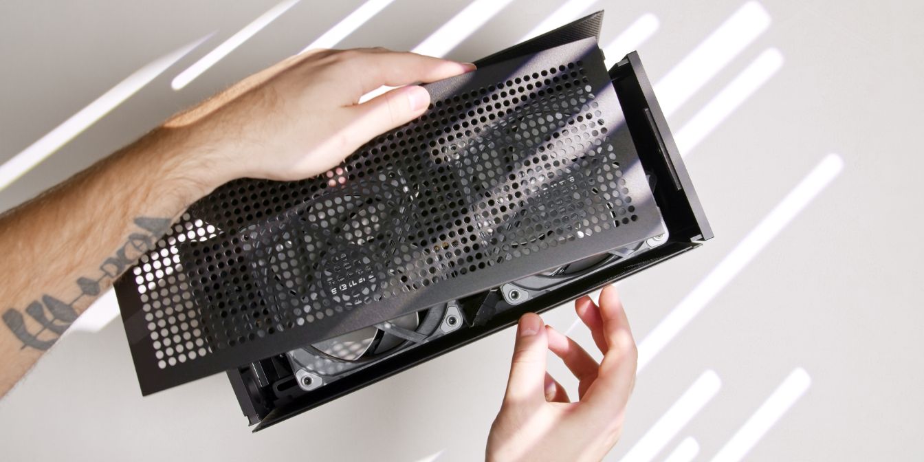
While holding the top panel, grab both side panels and push them in towards the case, then carefully place the top panel over them.
Insert the panel at a slight angle, taking note of the two metal tabs that need to go under the “lip” of the front panel.
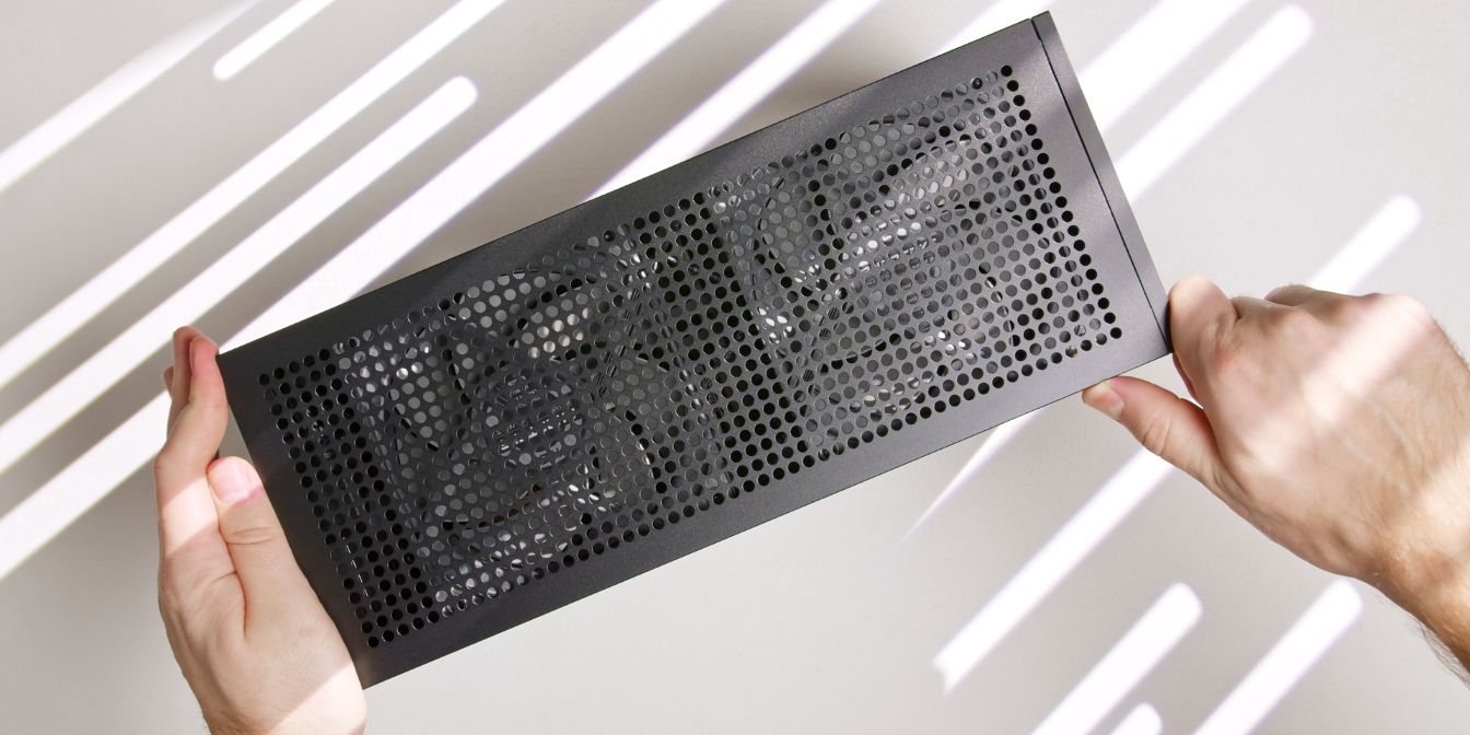
You may need to push the top panel into the front panel with some force.
If the side panels rub against the edges of either the front or back panels and top panel installation is difficult, your T1 might be out of square, check squaring steps listed in the previous section.
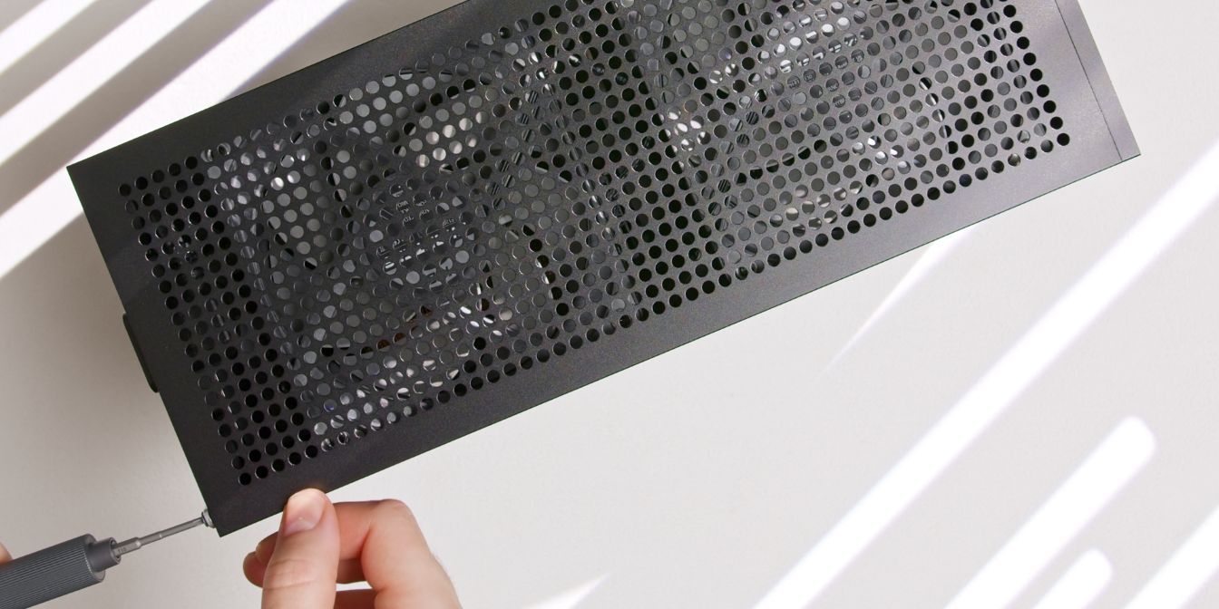
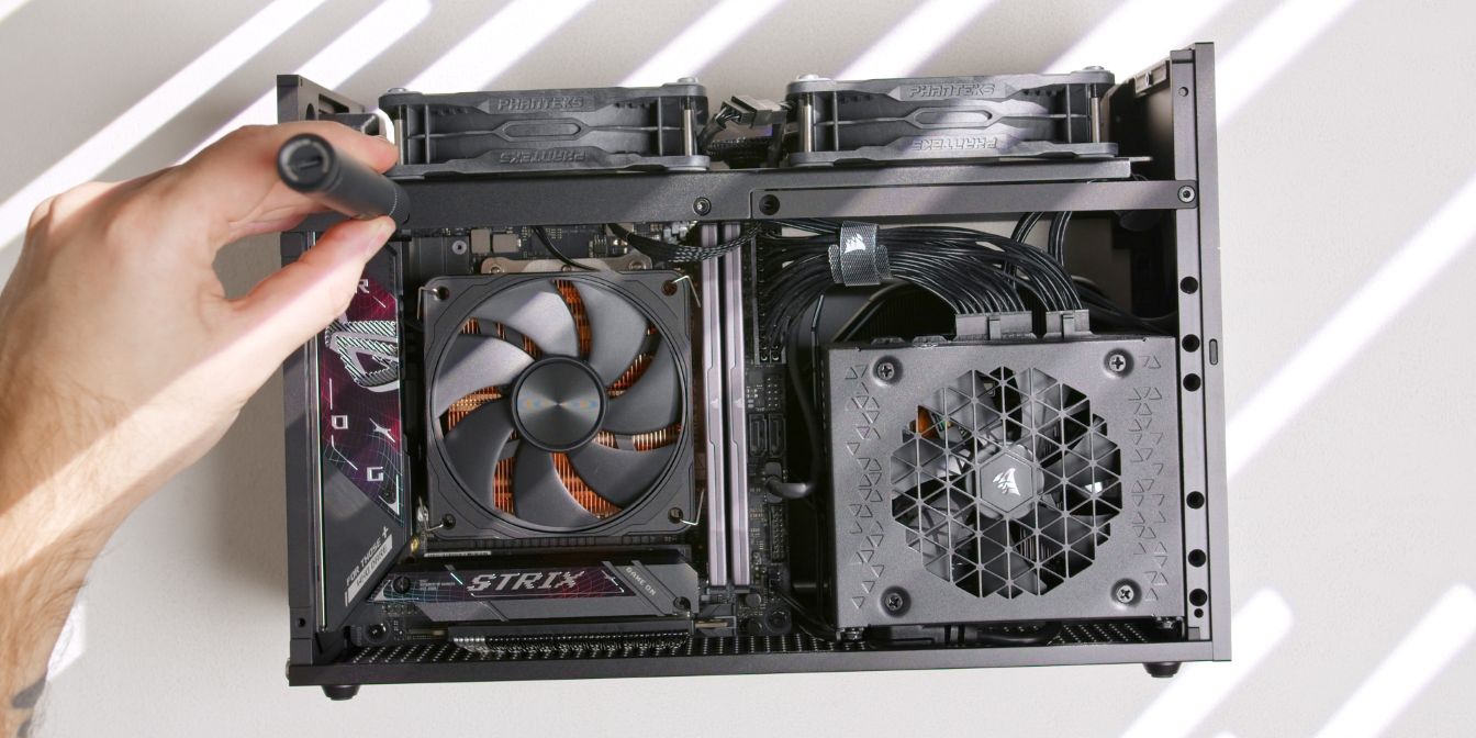
Finally, secure the top panel to the rear panel with two of the included M3 thumb screws.
Instead of thumb screws, I’m using the same style washers as for the exhaust fans, together with 12mm long Torx screws. See: Screws.
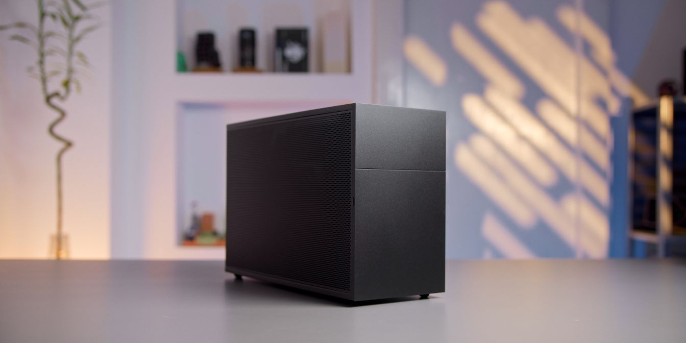
And with that, we’re done with assembly 🎉
If you’ve found any mistakes, inaccuracies or missing information, please contact me.